ASK RF-Transmitter(433MHZ) :
Are you looking for RF data transmission? Yes you are at right place just look at the transmitter image there was two main components which are ASK RF Transmitter (Amplitude Shift Keying Radio Frequency) and HT12E- Data Encoder IC. From this circuit you can send 4-bit data using that D0-D3 pins. A0-A7 are called as address lines 8 bit address lines can be connected to 256 devices (28=256) this transmitter operates at 5V.
 |
| RF 433MHz Trabsmitter |
ASK RF-Receiver (433MHZ):
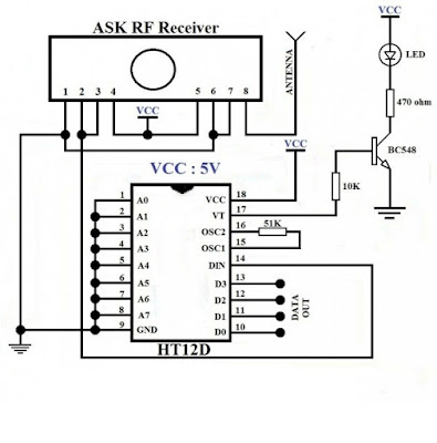
The following image shows that RF-receiver circuit. here main parts are Receiver and HT12D which means Decoder IC. Just make the connections as like that circuit diagram and the output can be collected from the Dout pins D0-D3. From the decoder 17 pin we can get the connection signal status whether transmitter is enabled or disabled. the transmitter and receiver will match only if both address are same otherwise it will not match.
 |
RF 433MHz Receiver
|


0 comments:
Post a Comment