Saturday 13 August 2016

Basics of Electronics and fundamentals

Definition of electronics: 

Electronics is the branch of science that deals with the study of flow and control of electrons (electricity) and the study of their behaviour and effects in vacuums, gases, and semiconductors, and with devices using such electrons. This control of electrons is accomplished by devices that resist, carry, select, steer, switch, store, manipulate, and exploit the electron.
What is electronics, resistor, inductor, voltage, current, instrumentation, activa and passive components, what is electronics, what is resistor, what is current, what is voltage, what is instrumentation, what is active components, what is  voltage
Electronics

Definition of instrumentation:

Instrumentation is the use of measuring instruments to monitor and control a process. It is the art and science of measurement and control of process variables within a production, laboratory, or manufacturing area.

An instrument is a device that measures a physical quantity such as flow, temperature, level, distance, angle, or pressure. Instruments may be as simple as direct reading thermometers or may be complex multi-variable process analyzers.

Some of the basic electrical units and definitions are mentioned below: 

Passive: Capable of operating without an external power source. Typical passive components are resistors, capacitors, inductors, and diodes (although the latter is a special case).

Active: Requiring a source of power to operate.    Includes transistors (all types), integrated circuits (all types), TRIACs, SCRs, LEDs, etc.
What is electronics, resistor, inductor, voltage, current, instrumentation, activa and passive components, what is electronics, what is resistor, what is current, what is voltage, what is instrumentation, what is active components, what is  voltage
Active and Passive Components


DC: Direct Current: The electrons flow in one direction only.  Current flow is from negative to positive, although it is often more convenient to think of it as from positive to negative.  This is sometimes referred to as "conventional" current as opposed to electron flow.

AC: Alternating Current: The electrons flow in two directions in a cyclic manner, first one way, and then the other.  The rate of change of direction determines the frequency, measured in Hertz (cycles per second).
What is electronics, resistor, inductor, voltage, current, instrumentation, activa and passive components, what is electronics, what is resistor, what is current, what is voltage, what is instrumentation, what is active components, what is  voltage
AC and DC


Frequency: Unit is Hertz, Symbol is Hz, the old symbol was cps (cycles per second). A complete cycle is completed when the AC signal has gone from zero volts to one extreme, back through zero volts to the opposite extreme, and returned to zero.  The accepted audio range is from 20Hz to 20,000Hz.  The number of times the signal completes a complete cycle in one second is the frequency. 
Frequency


Voltage: Unit is Volts, Symbol is V or U, an old symbol was E. Voltage is the "pressure" of electricity, or "Electro Motive Force" (hence the old term E).

Current: Unit is Amperes (Amps), Symbol is I. The amount of electrical charge is flow in a conducting material is called current. Current is measured in Amperes, which is Coulombs per Second.

Resistance: Unit is Ohms, Symbol is R or Ω. Resistance is a measure of how easily (or with what difficulty) electrons will flow through the device. 
A Resistor is an electrical device that resists the flow of electrical current.
Ohms Law, Voltage, Current, resistance, What is electronics, resistor, inductor, voltage, current, instrumentation, activa and passive components, what is electronics, what is resistor, what is current, what is voltage, what is instrumentation, what is active components, what is  voltage
Voltage, Current, and Resistance


Sunday 31 July 2016

Arduino Open-Source Community for Embeddians

Arduino is an open-source computer hardware and software company, project and user community that designs and manufactures Microcontroller-based kits for building digital devices and interactive objects (Embedded Projects) that can sense and control objects in the physical world.

Embeddworld, embedded projects, embedded systems, embedded, Arduino, Arduino projects, Arduino embedded projects, Arduino tutorials, Arduino download, Arduino Due, Arduino Gemma, Arduino Leonardo and Micro, Arduino Mini, Arduino Nano, Arduino Pro, Arduino Pro Mini, Arduino Yún, Arduino Zero, Arduino 101, Ethernet Shield, GSM Shield, Intel Edison, Intel Galileo Gen2, LilyPad Arduino, LilyPad Arduino USB
Arduino Open source community 


The project is based on software embedded on Microcontrollers. The arduino developments board designs manufactured by several vendors, using various Microcontrollers. These systems provide sets of digital and analog I/O pins that can be interfaced to various expansion boards ("shields") and other circuits like arduino with external breadboard connections. The arduino development board has a feature of in-built serial communications interfaces, including USB on some models, for loading programs from personal computers (PC). For programming the Microcontrollers, the Arduino project provides an integrated development environment (IDE) based on the Processing project, which includes support for the C and C++ programming languages. You can download Arduino IDE from here its an open source IDE and very simple to install click here to download


The first Arduino was introduced in 2005, aiming to provide an inexpensive and easy way for novices and professionals to create devices that interact with their environment using sensors and actuators. Common examples of such devices intended for beginner hobbyists include simple robots, thermostats, and motion detectors.

Arduino boards are available commercially in pre-assembled form, or as do-it-yourself kits. The hardware design specifications are openly available, allowing the Arduino boards to be manufactured by anyone. The Arduino development boards are available in online shopping websites also.

Arduino Development boards:

Embeddworld, embedded projects, embedded systems, embedded, Arduino, Arduino projects, Arduino embedded projects, Arduino tutorials, Arduino download, Arduino Due, Arduino Gemma, Arduino Leonardo and Micro, Arduino Mini, Arduino Nano, Arduino Pro, Arduino Pro Mini, Arduino Yún, Arduino Zero, Arduino 101, Ethernet Shield, GSM Shield, Intel Edison, Intel Galileo Gen2, LilyPad Arduino, LilyPad Arduino USB
LilyPad Arduino USB

Embeddworld, embedded projects, embedded systems, embedded, Arduino, Arduino projects, Arduino embedded projects, Arduino tutorials, Arduino download, Arduino Due, Arduino Gemma, Arduino Leonardo and Micro, Arduino Mini, Arduino Nano, Arduino Pro, Arduino Pro Mini, Arduino Yún, Arduino Zero, Arduino 101, Ethernet Shield, GSM Shield, Intel Edison, Intel Galileo Gen2, LilyPad Arduino, LilyPad Arduino USB
Arduino 101

Embeddworld, embedded projects, embedded systems, embedded, Arduino, Arduino projects, Arduino embedded projects, Arduino tutorials, Arduino download, Arduino Due, Arduino Gemma, Arduino Leonardo and Micro, Arduino Mini, Arduino Nano, Arduino Pro, Arduino Pro Mini, Arduino Yún, Arduino Zero, Arduino 101, Ethernet Shield, GSM Shield, Intel Edison, Intel Galileo Gen2, LilyPad Arduino, LilyPad Arduino USB
Arduino YUN

Embeddworld, embedded projects, embedded systems, embedded, Arduino, Arduino projects, Arduino embedded projects, Arduino tutorials, Arduino download, Arduino Due, Arduino Gemma, Arduino Leonardo and Micro, Arduino Mini, Arduino Nano, Arduino Pro, Arduino Pro Mini, Arduino Yún, Arduino Zero, Arduino 101, Ethernet Shield, GSM Shield, Intel Edison, Intel Galileo Gen2, LilyPad Arduino, LilyPad Arduino USB
Arduino DUE

Embeddworld, embedded projects, embedded systems, embedded, Arduino, Arduino projects, Arduino embedded projects, Arduino tutorials, Arduino download, Arduino Due, Arduino Gemma, Arduino Leonardo and Micro, Arduino Mini, Arduino Nano, Arduino Pro, Arduino Pro Mini, Arduino Yún, Arduino Zero, Arduino 101, Ethernet Shield, GSM Shield, Intel Edison, Intel Galileo Gen2, LilyPad Arduino, LilyPad Arduino USB
Arduino MEGA

Embeddworld, embedded projects, embedded systems, embedded, Arduino, Arduino projects, Arduino embedded projects, Arduino tutorials, Arduino download, Arduino Due, Arduino Gemma, Arduino Leonardo and Micro, Arduino Mini, Arduino Nano, Arduino Pro, Arduino Pro Mini, Arduino Yún, Arduino Zero, Arduino 101, Ethernet Shield, GSM Shield, Intel Edison, Intel Galileo Gen2, LilyPad Arduino, LilyPad Arduino USB
Arduino UNO


Embeddworld, embedded projects, embedded systems, embedded, Arduino, Arduino projects, Arduino embedded projects, Arduino tutorials, Arduino download, Arduino Due, Arduino Gemma, Arduino Leonardo and Micro, Arduino Mini, Arduino Nano, Arduino Pro, Arduino Pro Mini, Arduino Yún, Arduino Zero, Arduino 101, Ethernet Shield, GSM Shield, Intel Edison, Intel Galileo Gen2, LilyPad Arduino, LilyPad Arduino USB
Arduino MEGA2560 R3


Embeddworld, embedded projects, embedded systems, embedded, Arduino, Arduino projects, Arduino embedded projects, Arduino tutorials, Arduino download, Arduino Due, Arduino Gemma, Arduino Leonardo and Micro, Arduino Mini, Arduino Nano, Arduino Pro, Arduino Pro Mini, Arduino Yún, Arduino Zero, Arduino 101, Ethernet Shield, GSM Shield, Intel Edison, Intel Galileo Gen2, LilyPad Arduino, LilyPad Arduino USB
Arduino LEONARDO


Embeddworld, embedded projects, embedded systems, embedded, Arduino, Arduino projects, Arduino embedded projects, Arduino tutorials, Arduino download, Arduino Due, Arduino Gemma, Arduino Leonardo and Micro, Arduino Mini, Arduino Nano, Arduino Pro, Arduino Pro Mini, Arduino Yún, Arduino Zero, Arduino 101, Ethernet Shield, GSM Shield, Intel Edison, Intel Galileo Gen2, LilyPad Arduino, LilyPad Arduino USB
Arduino DUEMILANOVE

Embeddworld, embedded projects, embedded systems, embedded, Arduino, Arduino projects, Arduino embedded projects, Arduino tutorials, Arduino download, Arduino Due, Arduino Gemma, Arduino Leonardo and Micro, Arduino Mini, Arduino Nano, Arduino Pro, Arduino Pro Mini, Arduino Yún, Arduino Zero, Arduino 101, Ethernet Shield, GSM Shield, Intel Edison, Intel Galileo Gen2, LilyPad Arduino, LilyPad Arduino USB
Arduino DIECIMILA

Embeddworld, embedded projects, embedded systems, embedded, Arduino, Arduino projects, Arduino embedded projects, Arduino tutorials, Arduino download, Arduino Due, Arduino Gemma, Arduino Leonardo and Micro, Arduino Mini, Arduino Nano, Arduino Pro, Arduino Pro Mini, Arduino Yún, Arduino Zero, Arduino 101, Ethernet Shield, GSM Shield, Intel Edison, Intel Galileo Gen2, LilyPad Arduino, LilyPad Arduino USB
LilyPad Arduino

Embeddworld, embedded projects, embedded systems, embedded, Arduino, Arduino projects, Arduino embedded projects, Arduino tutorials, Arduino download, Arduino Due, Arduino Gemma, Arduino Leonardo and Micro, Arduino Mini, Arduino Nano, Arduino Pro, Arduino Pro Mini, Arduino Yún, Arduino Zero, Arduino 101, Ethernet Shield, GSM Shield, Intel Edison, Intel Galileo Gen2, LilyPad Arduino, LilyPad Arduino USB
Arduino nano


LM 35 Temperature Sensor Details

LM 35 is a accurate temperature sensor. Which is tiny in size and can be interface to the any type of Microcontroller available in market. The LM stands for Linear Monolithic which is made by Texas Instruments.
LM35 Temperature sensor Pin Out Details
This LM35 is a simple and easy to interface with any type of Microcontroller and the calculation is done below here for all platforms. LM35 will operate 4-30 Vdc and it will consume only 60uA current. In this LM35 will sense the temperature between−55°C to 150°C Range and will produce   10mV for 1°C changes in the sensor. Using this sensor we can measure room temperature and outdoor and indoor temperature but its not suitable to measure the human being temperature for that you may go to some Bio- temperature sensors from the same Texas instruments products.

Special features of the LM35:

  • Calibrated Directly in Celsius (Centigrade)
  • Linear + 10-mV/°C Scale Factor
  • Rated for Full −55°C to 150°C Range
  • Suitable for Remote Applications
  • Low-Cost Due to Wafer-Level Trimming
  • Suitable for Remote 
  • Low-Cost Due to Wafer-Level Trimming scaling. 
  • Operates from 4 V to 30 V
  • Less than 60-μA Current Drain 
  • Low Self-Heating, 0.08°C in Still Air 
  • Non-Linearity Only ±¼°C Typical
  • Low-Impedance Output, 0.1 Ω for 1-mA Load

LM35 interfacing calculation:

To interface this LM35 to your Microcontroller you must know about the ADC channel which is using and its output range. Here i have stated the calculation for 10 bit ADC output which gives 1024 steps (210=1024).

Formula:

Temperature=((ADC value * Reference voltage in milli volts)/(ADC steps* LM35 out));

 example:

Temperature= ((ADC value*5*1000)/(1024*10));
after simplification Temperature=(ADC value*0.4882); will gives you the temperature as a result.

Here,

 Temperature = May be defined as int or float,
ADC value    = From the Microcontroller
5  is for          = Reference voltage in volts
1000 is for     = Volts to milli Volts conversion
1024 is for     = ADC step resolution (10 bit)
10 is for         = LM35 output for 1°C =10mV if the LM35 gives (1500mV=150°C, 1000mV=100°C, 400mV=40°C)
Now you can do the calculation for any kind of Microcontroller .

Datasheet download from here: LM35 


PIC Microcontroller Programming Software IDE Free download

PIC Microcontrollers are manufactured by microchip technologies they are in series of 8-bit and 16-bit, 24-bit, 32-bits an more over they are manufacturing many digital signal processors and embedded processors also if you want to buy Microcontrollers just visit here

Microcontroller IDE (Integrated Development Environment):

Here the IDE's are playing major role in programming the microcontrollers. You can ask what is meant by IDE and why it is necessary ?. Yes your question is correct the answer is: we know only alphabets and numbers but machines ( microcontrollers) only knows digital signals 0's and 1's so the IDE will do the conversion between human language to machine.
Microcontroller IDE, mikcro c pro for pic, mikroc, MPLAB, MPLABX, MPLABx COmpiler, Mplabxc8,

 MPLABX-IDE:

I strongly suggest two IDE for you people with my experience. The original microchip and their own Microcontroller IDE is MPLABX  you can click the download button to download MPLABX IDE to your devices. One more thing is that you should download compiler also and don't worry we give you that link also.
Microcontroller IDE, mikcro c pro for pic, mikroc, MPLAB, MPLABX, MPLABx COmpiler, Mplabxc8,

To download the MPLABX IDE click here:

Microcontroller IDE, mikcro c pro for pic, mikroc, MPLAB, MPLABX, MPLABx COmpiler, Mplabxc8,

To download the XC8 compiler click here:

Microcontroller IDE, mikcro c pro for pic, mikroc, MPLAB, MPLABX, MPLABx COmpiler, Mplabxc8,

MIKROC PRO for PIC-IDE:

If you are a beginner i suggest this mikroC pro for PIC. This IDE has inbound function to write the microcontroller programming. Easy to program and user-friendly software to use and program the PIC microcontroller.
Microcontroller IDE, mikcro c pro for pic, mikroc, MPLAB, MPLABX, MPLABx COmpiler, Mplabxc8,

To download Mikroc PRO for PIC

Microcontroller IDE, mikcro c pro for pic, mikroc, MPLAB, MPLABX, MPLABx COmpiler, Mplabxc8,

Just try those compilers and IDE any help just contact us to provide more details.


433MHZ RF Transmitter and Receiver Circuit Diagram

ASK RF-Transmitter(433MHZ) :

Are you looking for RF data transmission? Yes you are at right place just look at the transmitter image there was two main components which are ASK RF Transmitter (Amplitude Shift Keying Radio Frequency) and HT12E- Data Encoder IC. From this circuit you can send 4-bit data using that D0-D3 pins. A0-A7 are called as address lines 8 bit address lines can be connected to 256 devices (28=256) this transmitter operates at 5V.
433MHZ RF circuit, ASK RF transmitter and receiver circuit diagram, circuit images, RF transmitter and receiver circuit diagram, wireless communication, wireless data transfer, wireless protocol, wireless transmitter and reciever,
RF 433MHz Trabsmitter

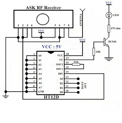
ASK RF-Receiver (433MHZ):

The following image shows that RF-receiver circuit. here main parts are Receiver and HT12D which means Decoder IC. Just make the connections as like that circuit diagram and the output can be collected from the Dout pins D0-D3. From the decoder 17 pin we can get the connection signal status whether transmitter is enabled or disabled. the transmitter and receiver will match only if both address are same otherwise it will not match.
433MHZ RF circuit, ASK RF transmitter and receiver circuit diagram, circuit images, RF transmitter and receiver circuit diagram, wireless communication, wireless data transfer, wireless protocol, wireless transmitter and reciever,
RF 433MHz Receiver


Printed Circuit Board (PCB) Software Free download

A Printed Circuit Board (PCB) mechanically supports and electrically connects electronic components using conductive tracks, pads and other features etched from copper sheets laminated onto a non-conductive substrate. Components - capacitors, resistors or active devices - are generally soldered on the PCB. Advanced PCBs may contain components embedded in the substrate-WIKI.

PCB design , PCB, Printed circuit, PCB, Printed circuit board, Techparkz,


PCB design , PCB, Printed circuit, PCB, Printed circuit board, Techparkz,


To download the DipTrace software click here:

Saturday 23 July 2016

5V to 3.3V Logic Level Converter Circuit

We all know that 20th-century electronic devices are worked in 5-Voltage and more than that and 21st century starts and running on below 5Volts I mean 3.3V and 1.8V so we need to make a logic converter here like a bridge between 5V to 3.3V devices to operate or may be to control. Here the fig shown below is act as a logic converter from 5V to 3.3V. The BSS138 is a MOSFET if not available that equivalent MOSFET is 2N7000 so no need to worry about it make a change and work it out. These converters are used for engineering projects, domestic applications, used as hobbies, mini projects, prototypes, and etc applications.

Circuit diagram for 5V to 3.3V logic converter:

  1. On top of the image shown in below you have to connect 3.3V & 5V voltage source (power supply)
  2. Tx-3.3V is from Arduino, Raspberry pi, ESP8266, and Intel boards.
  3. Tx-5V to be connected with peripheral devices like relay, ULN2003, and driver circuits and actuators
3.3V to 5V logic converter, voltage shifter, logic shifter, voltage converter, voltage booster, voltage converter, 5V to 3.3V converter
5V to 3.3V logic converter

Pin diagram of BSS138:

The pin diagram shows the internal and type of package available in market. Click here to download the Datasheet for BSS138
3.3V to 5V logic converter, voltage shifter, logic shifter, voltage converter, voltage booster, voltage converter, 5V to 3.3V converter, BSS138 PIN DIAGRAM
Pin Diagram of BSS138 MOSFET

Pin diagram of 2N7000:

There is an another way to make the circuit with 2N7000 MOSFET. Because the BSS138 is not available in local area electronics so this 2N7000 is an equivalent for the BSS138 with same functionalities. There is no external diode need for this MOSFET because in this BSS138 and 2N7000 has In-built Freewheeling diode. This circuit can be utilized for Arduino to Raspberry pi, ESP8266, Bluetooth HC-05 module, all external modules which are working under 3.3V can be interfaced with this 3.3V to 5V logic converter.


2N7000 pin diagram,3.3V to 5V logic converter, voltage shifter, logic shifter, voltage converter, voltage booster, voltage converter, 5V to 3.3V converter

Feel free to comment here:

If the circuit not working or any other clarifications you can contact us with pleasure. If you hope this blog is useful share with your friends 

Friday 17 June 2016